How to Build and Install on Your Machine
How to Build,Get, & Install on Your Machine
- Purchase an Arduino Mega 2560 pro like this one
- Get an interface board (RoyGBev sells them on Pinside) If the board is pre-flashed skip the downloading and compiling sections
- Download the code for your game, compile, and install it on your ardiuno
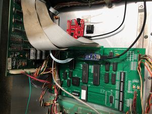
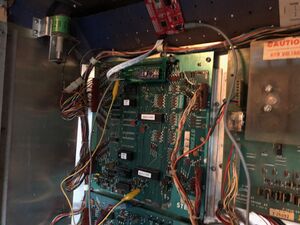
- Install it onto your MPU board via the J5 connector
- Install a remote switch or jumper to enable/disable the original code on your machine
- Purchase a WAV trigger from Amazon or SparkFun
- Upgrade the WAV trigger to version 1.3 or higher
- Download and load the sounds for your machine onto the micro SD Card and insert it into the WAV trigger
- Bridge the 5V input power pad on the WAV trigger
- Connect the WAV trigger to the interface board - making sure to pay attention to the pin order
- Hook up a set of powered speakers to the WAV trigger
- Turn on the machine and play!
Downloading and compiling the code
The code for the machines is written in Arduino (Based on C++)
- To download the pinball machine BSOS code, go to the GitHub repository page for the machine you are installing (See the list of machines and the git libraries). On the right side of the page, you should see a green button that says "Code". Click this button and then select "Download ZIP" from the dropdown menu. This will download a zip file containing the code and all of its associated files to your computer.
- Once the download is complete, unzip the file to a location on your computer where you want to store the code.
- Next, open the Arduino IDE. From the File menu, select "Open" and navigate to the folder where you unzipped the pinball machine BSOS code. Open the file with the ".ino" extension. This will load the code into the IDE.
- Before you can upload the code to the Arduino Mega 2560, you will need to set the correct board and serial port in the IDE. To do this, go to the Tools menu and select the "Board" and "Port" options. Choose "Arduino/Genuino Mega or Mega 2560" as the board and the serial port that your Arduino is connected to as the port.
- Finally, to upload the code to the Arduino, click the "Upload" button in the IDE (it looks like an arrow pointing to the right). This will compile the code and send it to the Arduino, where it will be run. If the upload is successful, you should see a message in the IDE indicating that it was completed.
Installing the card onto the J5 connector
Your MPU should be working before you attempt this step. There are some situations where you can use this daughter card without parts of your MPU functioning. For example, the new code will not require the PROMs, RAM, CRAM, or reset section of the board to be operable. However, until you know your MPU is in working order, I advise you to start there.
With the machine off, plug in your new card into J5, ensuring that the rightmost pin (pin 1) of the daughter card is connected to the rightmost pin (pin 1) of J5. The J5 connector is keyed on pin 29, for reference.
On a Bally AS-2518-17, -35, or Stern MPU-100 board, the J5 connector doesn’t contain the IRQ line. For those boards, you’ll need to run a jumper between the Arduino’s pin D2 and the top leg of R134
On a Stern MPU-200 or an Alltek MPU Replacement (Bally/Stern), the J5 connector is 34 pins and it contains an IRQ line on pin 34. For these boards, the daughter card can pick up the IRQ directly from the board.

