RPU Hardware Revisions
RPU Hardware Revisions
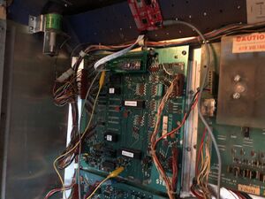
Interfacing the Arduino to the MPU is done using the J5 connector on the board. The J5 connector is at the top of the board and it was originally meant as a diagnostic port. It contains access to all the lines needed except for the IRQ line on the original MPU's.
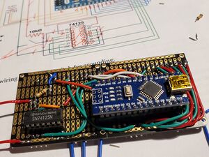
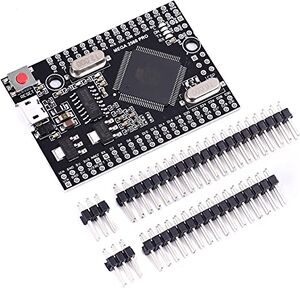
The hardware interface board has gone through several revisions. The original version interfaced with an Arduino Nano, though due to program space limitations and the need for additional pins current versions use the Arduino Mega 2560 Pro.
| Board Version | Arduino Required | Compatible
Bally MPUs |
Compatible
Stern MPUs |
Compatible
Williams MPUs |
Bally Sound Cards | Stern Sound Cards | Willams Sound Cards | Boots
Original Code |
|---|---|---|---|---|---|---|---|---|
| Revision 1 | NANO ATMega328P | AS-2518-17
AS-2518-35 |
MPU-100
MPU-200 |
-21, -50, -51 | Hardware switch | |||
| Revision 2 | NANO ATMega328P | AS-2518-17
AS-2518-35 |
MPU-100
MPU-200 |
-21, -50, -51 | SB-100 | Hardware switch | ||
| Revision 3 | MEGA 2560 PRO | AS-2518-17
AS-2518-35 |
MPU-100
MPU-200 |
-21, -50, -51 | SB-100, SB-300 | Hardware switch | ||
| Revision 4 | MEGA 2560 PRO | AS-2518-17
AS-2518-35 |
MPU-100
MPU-200 |
-21, -50, -51 | SB-100, SB-300 | Hardware switch
or hold Credit/Reset button on boot | ||
| Revision 101 | MEGA 2560 PRO | AS-2518-17
AS-2518-35 |
MPU-100
MPU-200 |
System 4
System 6 System 6a System 7 System 11 |
-21, -50, -51 | SB-100, SB-300 | Type 1
Type 2 System 11 Sound System 11 Music |
Hardware switch
or hold Credit/Reset button on boot |
| Revision 102
(auto detects CPU) |
MEGA 2560 PRO | AS-2518-17
AS-2518-35 |
MPU-100
MPU-200 |
System 4
System 6 System 6a System 7 System 11 |
-21, -50, -51 | SB-100, SB-300 | Type 1
Type 2 System 11 Sound System 11 Music |
Hardware switch
or hold Credit/Reset button on boot |
Early Prototypes
The earliest versions of the BSOS system were based on breadboards - manual versions of what would eventually become Version 1.
Version 1
Revision 1 uses a 74125 buffer chip to interface an Arduino NANO to the MPU. This board works for most Bally -17, -35, and Stern -100, and -200 games, but won't allow the NANO to control the SB300 (like in Meteor and Galaxy).
Version 2
Revision 2 uses two ICs (74155 & 74240) to interface more thoroughly. It can talk to the SB300.
Version 3
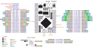
Revision 3 upgrades the Arduino to a MEGA 2560 PRO and works with all Bally/Stern early SS games (NOTE: the MEGA 2560 PRO has a different layout than a typical MEGA 2560. You need a MEGA 2560 PRO with D0-D31 on the same header)
Version 4 - in-progress
IRQ Line
On the original MPU boards (Altek replacement boards have the IRQ line on J5) a jumper from top lead of R134 on the MPU board needs to be connected to the IRQ pin on the interface board so the Arduino can sense the interrupt line.
WAVTrigger board
WAVTrigger is a separate add-on board that receives signals via a serial port and can play sounds from an SD card.
Installing the card onto the J5 connector
Your MPU should be working before you attempt this step. There are some situations where you can use this daughter card without parts of your MPU functioning. For example, the new code will not require the PROMs, RAM, CRAM, or reset section of the board to be operable. However, until you know your MPU is in working order, I advise you to start there.
With the machine off, plug in your new card into J5, ensuring that the rightmost pin (pin 1) of the daughter card is connected to the rightmost pin (pin 1) of J5. The J5 connector is keyed on pin 29, for reference.
On a Bally AS-2518-17, -35, or Stern MPU-100 board, the J5 connector doesn’t contain the IRQ line. For those boards, you’ll need to run a jumper between the Arduino’s pin D2 and the top leg of R134
On a Stern MPU-200 or an Alltek MPU Replacement (Bally/Stern), the J5 connector is 34 pins and it contains an IRQ line on pin 34. For these boards, the daughter card can pick up the IRQ directly from the board


